Inductor Adjustable by Discrete Steps
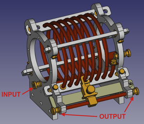
- Quick manual adjustment
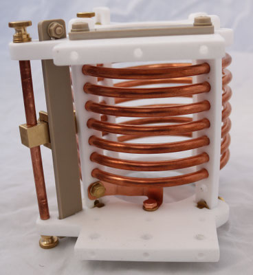
- 100mm diameter air-core coil
- 6mm diameter copper tube
-
10 models: 3 turns (1μH) to 12 turns (8μH)
- Air-cooled up to 2kW CW at 13.56MHz
- High temperature rating (≤200°C)


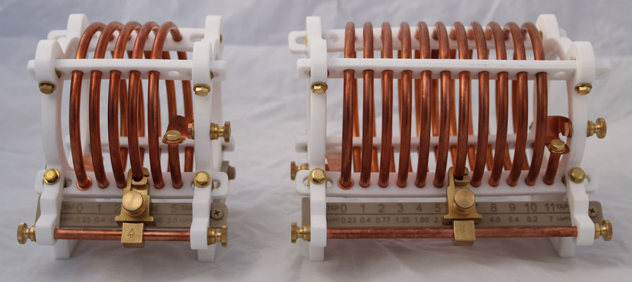
Click on the photos above to zoom in
About this Inductor
- I developed this inductor because I wasn't satisfied with the off-the-shelf inductors available on the market I was using to make the matching networks of my customers. They were too resistive, fragile and cumbersome to adjust.
- This easy-to-use stand-alone inductor is optimized for high RF power applications. It is made without any compromise regarding the materials used (PTFE, PEEK, copper and brass) and its performances. It maintains its shape and set inductance value up to 200°C.
Choose Your Model

| Reference |
Max Number of Turns |
Length (mm) at the Base (± 1mm) |
Max Inductance (μH) at 300kHz |
Quality Factor at 13.56MHz at Max Inductance |
Resistance (Ω) at 13.56MHz at Max Inductance |
| Di-D100-T3 | 3 | 73 | 1.25 | 750 | 0.14 |
| Di-D100-T4 | 4 | 84 | 1.86 | 900 | 0.18 |
| Di-D100-T5 | 5 | 95 | 2.5 | 1050 | 0.2 |
| Di-D100-T6 | 6 | 106 | 3.2 | 1150 | 0.24 |
| Di-D100-T7 | 7 | 117 | 3.9 | 1200 | 0.28 |
| Di-D100-T8 | 8 | 128 | 4.6 | 1250 | 0.31 |
| Di-D100-T9 | 9 | 139 | 5.4 | 1300 | 0.35 |
| Di-D100-T10 | 10 | 150 | 6.2 | 1300 | 0.41 |
| Di-D100-T11 | 11 | 161 | 7 | 1300 | 0.46 |
| Di-D100-T12 | 12 | 172 | 7.8 | 1300 | 0.51 |
Measured Electrical Parameters

The inductance as a function of the number of turns is the same whatever the model. This is not the case for the losses (see below).


The unused turns increase the losses: the larger the tuning range the higher the resistance (lower quality factor).
Dimensions

